A World Class Example of
Adaptive Engineering
by
Ken W. Watson
Note: This article first appeared in the Spring/Summer 2019 edition of Rideau Reflections, the newsletter of the Friends of the Rideau (www.rideaufriends.com).
| |  |
| |
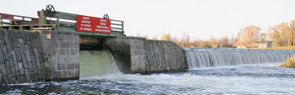
Weir and Overflow Dam at Edmunds Lockstation
|
In our Fall/Winter 2018 newsletter it was noted that the Rideau Canal made the list of top 200 Engineering projects of the last 200 years (as determined by the Institution of Civil Engineers). One of the reasons is that it is a world class example of adaptive engineering, coming up with engineering solutions to meet local conditions and trying different engineering methods during construction to see which would work the best. This is unlike engineering projects of today where everything is pre-determined to the millimetre before the first shovel hits the ground.
The best known example of adaptive engineering is the use of waste weirs on the Rideau Canal. Those familiar with the history of the Rideau Canal know that these were not originally planned. The first design was for the main dams to be overflow dams, the height of the water simply regulated by the height of the dam. However, Colonel By’s experience with spring flooding on the Rideau showed him that he had to make engineering changes. His solution was to have waste water weirs as an “indispensably necessary” addition to most of the lockstations. For example, in his 1830 report for Black Rapids he wrote:
“Having observed that the Spring floods flowing over the Dam, had a great effect upon the Bed of the River immediately in front of the same, by tearing up the Strata, I considered it indispensably necessary to provide for the safety of the Dam, and conceived that a Waste Weir, sufficiently wide to allow a large portion of the Water of the River to pass through it during the Spring floods, was the safest as well as the cheapest mode that could be adopted, and I am happy in being able to state, that this work completely answered the purpose desired in the Spring.”
His engineering solutions were not cookie cutter solutions, he was also trying out different engineering solutions at different lockstations. An example of this that can still be seen today is the design of the tunnel sluices. Tunnel sluices are the openings in the large foundation (the breastwork) at the head of most locks that allow the water from above the lock to flow into the lock chamber. The sluices channel the water into the head of each lock chamber at a 90 degree angle to minimize turbulence in the lock. At the original 1832 locks with tunnel sluices, two different engineering designs were used.
At most lockstations, the original design was to place a sluice valve in the middle of the tunnel. That valve would be opened and closed using a crab (hand winch). A square manhole provided access to the sluice valve mechanism. However, at two of the locks, Kingston Mills and Jones Falls, a different engineering design was used, one using face valves, valves located on the upper wall at the entrance to each tunnel sluice. To prevent the sluice from air locking, a small vent in the middle of the tunnel was used. The vents at Kingston Mills have square covers, the vents at Jones Falls have round covers. Another difference is that at these locks, a rack and pinion system is used to open and close the valves rather than a crab. Colonel By planned to use rack and pinion controls for all the locks, but he changed the design for the in-tunnel valves, substituting iron valves in place of wooden valves and a crab and chain mechanism in place of the originally planned rack and pinion mechanism.
| |  |
| |
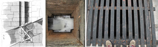
Manholes leading into tunnel sluices
The image on the left shows the original design of an in-tunnel valve. The middle picture is looking into a now empty manhole, to where the tunnel valve used to be prior to removal in 1839. The wooden grates that originally protected the manhole openings were replaced in 1900 with iron grates after the Superintendent of the Rideau Canal broke through a wooden cover in 1899 and got sluiced into a lock.
Left image from “Detailed description of some of the works on the Rideau Canal” by Lt. Denison, Papers on Studies connected with the Corps of Royal Engineers, Vol III, 1839. Photos by Ken W. Watson
|
With the opening of the Rideau Canal in 1832, they gained lots of real world experience in how these two different sluice mechanisms worked. The Rideau, as a newly flooded environment, had lots of debris, things such as branches coming off rotting trees in addition to the regular aquatic vegetation that would get uprooted, head to the locks and get caught up in the sluice valves. In addition, saw mills along the waterway were dumping large quantities of sawdust into the water and this also created sluice valve failures. The locks at Kingston Mills and Jones Falls, with their accessible face valves, were easy to maintain, but the other locks, with their in-tunnel valves, were much more difficult to maintain, as debris was much harder to clear from inside the tunnel.
| |  |
| |
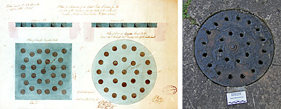
Tunnel Sluice Vent Covers
The diagram shows the engineering designs for the cast iron sluice vent covers for Kingston Mills (left) and Jones Falls (right) - drawn by Captain D. Bolton in 1836. The photo is of a current sluice vent cover at Jones Falls (photo by Ken W. Watson)
|
In 1839 the in-tunnel valves were removed and replaced by face valves. The now empty sluice tunnel manholes were covered over with wooden slats to prevent lock staff from accidently falling in. That worked until 1899 when Superintendent Philips, while on an inspection tour, broke through the wooden slats covering a manhole at the Long Island locks and got sluiced into the lock (with just a few bruises). Subsequent to that incident, he ordered that all wooden slat covers be replaced with iron slats, the ones we can see covering the manholes today.
There are many other examples of adaptive engineering along the Rideau. It’s to be remembered that they were still working out solutions in 1827 and 1828. Surveys of the sites were still being done 1827 and one of the engineers, N.H. Baird, was quoted in 1828 as stating that a solution to navigation through Smiths Falls “seems rather a puzzler.” The final decision to increase the size of the locks in June 1828 necessitated an engineering re-think at many of the lockstations. The locks at Ottawa for instance, were originally planned as two flights of four locks with a turning basin in the middle. That had to be changed to a single flight of 8 locks with the new larger sized locks.
At Hogs Back, the stone arch dam fell down three times during construction. The plan for that was abandoned in favour of a timber crib (stone filled) dam design, which still stands today. At the Ottawa locks, the sills moved due to hydraulic pressure during the first tests of the locks. Colonel By consulted with the contractors, Thomas MacKay and John Redpath, to come up with an engineering solution to fix that problem. When the lock at Upper Brewers was almost washed away in May 1832, due to the failure of a mill dam holding back the raised waters of Loughborough Lake, Colonel By came up with the design for a safety gate that would protect the lock – two such gates were installed, one at Upper Brewers and one at Newboro.
The fact that there is a lock in the middle of a lake (Narrows) is another example of an adaptive engineering solution to a construction problem, the hard and fractured bedrock at Newboro. Colonel By originally anticipated that he could simply dig a canal cut through the isthmus at Newboro (no lock). The survey he had showed only a small difference in water elevation between Rideau Lake and Mud (Newboro) Lake. But that survey was in error, the difference was greater than By anticipated and it now meant he had to put a lock into the channel. The hard and fractured bedrock at the Isthmus also came as a surprise, it was extremely difficult to excavate the channel as deep as it needed to go. By realized that if you couldn’t dig the channel deeper, a solution was to raise the water level in that channel. This led to the idea of building a dam and lock at a narrowing in Rideau Lake, the Upper Narrows, and raising the level of Upper Rideau Lake.
Testament to that story exists today with the lack of breastworks, the normal upper foundations for a lock, at Newboro and Narrows. While Colonel By didn’t have the technology to dig the channel as deep as he wanted to, he knew that at some point that technology would come along. So he didn’t plan for the locks at Newboro and Narrows to be permanent, he built them without breastworks (upper foundations), so that the locks could be removed when the time came that the channel at Newboro could be sufficiently deepened. That was never done, but lack of breastworks and the placement of sluice valves in the upper gates at Newboro and Narrows remain in testament to By’s engineering foresight.
When you’re out and about at the locks this summer, have a look at the weirs. See them as an engineering solution to a problem. Have a look at the manholes leading into the tunnel sluices. Contrast those with the small sluice vents at Jones Falls and Kingston Mills. They all tell the story of engineering the Rideau Canal.
-Ken W. Watson
|